2020年1月16日星期四

Oyostepper's Closed-Loop Stepper Motor Market Is Steadily Growth

The global stepper motor closed-loop market will show steady growth. The main factors driving the growth of the global closed-loop stepper motor market include the rapid growth of automation, the standardization of energy efficiency, the integration of motion control components and the low price compared to it. servo motor. However, operating a closed-loop stepper system at a higher speed is difficult, which is a major factor limiting its global market growth.

23hs41-1804s

The main trends observed in the global closed-loop stepper motor market include regulations for the evolution of energy efficiency and microstepping technology. These energy regulations are primarily developed through global warming and the global ecological environment. In addition, the development of Industry 4.0 is expected to provide tremendous opportunities to promote the growth of the global closed-loop stepper motor market.

The main trend observed in closed loop stepper motors is the integration of wireless communication technologies. Wireless technology is part of the automation that has been nurtured over the past decade. Although initial control is inconvenient, wireless technology has evolved rapidly from sensor-only to closed-loop control.

Closed-loop steppers can exhibit mechanical resonance at higher speeds and at specific step rates, so they can lose torque and synchronization. The development of microstepping technology has been seen as another major trend in the global closed-loop stepper motor market. Microstepping technology helps the motor run smoothly and overcomes several cogging and resonance related problems. This technology provides low-cost privileges for closed-loop steppers to improve their performance.


2020年1月15日星期三

Linear actuator falls into two basic categories

A linear stepper motor actuator is an actuator that creates motion in a straight line, in contrast to the circular motion of a conventional electric motor. Linear actuators are used in machine tools and industrial machinery, in computer peripherals such as disk drives and printers, in valves and dampers, and in many other places where linear motion is required. Hydraulic or pneumatic cylinders inherently produce linear motion. Many other mechanisms are used to generate linear motion from a rotating motor.


Linear actuator falls into two basic categories: belts type and ball screws type.

Belt type linear module mainly consists of: belt, linear guide, aluminum alloy profile, coupling, motor, photoelectric switch, etc.

Ball screw linear module mainly consists of: ball screw, linear guide rail, aluminum alloy profile, ball screw support seat, coupling, motor, photoelectric switch, etc.

Industry application field

Linear modules are widely used in dispensing; precision positioning and inspection of semiconductor liquid crystal devices; medical precision analyzer platform; machine tool industry (laser, EMD EDM); wafer inspection, three-coordinate inspection machine; large-scale printing, scanning, 3D printing Manufacturing, processing, experimental equipment; semiconductor manufacturing equipment; flat panel display (FPD) precision testing equipment; laser equipment, machine vision testing equipment; electronic components, PCB testing equipment; logistics equipment and other industries.

23LS26-25042-250E


MCB series linear sliding table typical application case:

Automated stepper motor assembly line X-axis Y-axis Z-axis linear slide

X axis:

1, effective stroke: 500mm

2, Repeat positioning accuracy: ±0.01mm

3, Speed: 100-200mm/s

4, ball screw: C7φ12

5, encoder resolution: 20000 pulses / circle

6, X-axis load 15KG

Y axis:

1, effective stroke: 500mm

2, Repeat positioning accuracy: ±0.01mm

3, Speed: 100-200mm/s

4, ball screw: C7φ12

5, encoder resolution: 20000 pulses / circle

6, X-axis load 15KG

Z axis:

1, effective stroke: 200mm

2, repeated positioning accuracy: ± 0.01mm

3, Speed: 50-100mm/s

4, ball screw: C7φ12

5, encoder resolution: 20000 pulses / circle

6, X-axis load 10KG2

How to Generate Power with a Step Motor
How to Choose a Excellent Extruder Stepping Motor for 3D Printer


2020年1月14日星期二

The principle of Variable Reluctance Stepper Motor

The principle of Variable Reluctance Stepper Motor is based on the property of the flux lines which capture the low reluctance path. The stator and the rotor of the motor are aligned in such a way that the magnetic reluctance is minimum. There are two types of the Variable Reluctance Stepper Motor. They are as follows
Working of a Variable Reluctance Stepper Motor
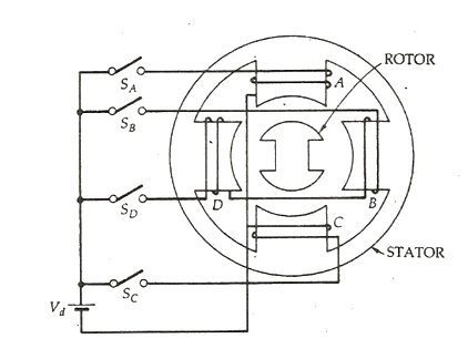
A four phase stepper motor or (4/2 pole), single stack variable reluctance stepper motor is shown below. Here, (4/2 pole) means that the stator has four poles and the rotor has two poles.
Variable Reluctance Stepper Motor fig 1
The four phases A, B, C and D are connected to the DC source with the help of a semiconductor, switches SA, SB, SC and SD respectively as shown in the above figure. The phase windings of the stator are energized in the sequence A, B, C, D, A. The rotor aligns itself with the axis of phase A as the winding A is energized. The rotor is stable in this position and cannot move until phase A is de-energized.
Now, the phase B is excited and phase A is disconnected. The rotor moves 90 degrees in the clockwise direction to align with the resultant air gap field which lies along the axis of phase B. Similarly the phase C is energized, and the phase B is disconnected, and the rotor moves again in 90 degrees to align itself with the axis of the phase
Thus, as the Phases are excited in the order as A, B, C, D, A, the rotor moves 90 degrees at each transition step in the clockwise direction. The rotor completes one revolution in 4 steps. The direction of the rotation depends on the sequence of switching the phase and does not depend on the direction of the current flowing through the phase. Thus, the direction can be reversed by changing the phase sequence like A, D, C, B, A.
The magnitude of the step angle of the variable reluctance motor is given as
variable-reluctance-stepper-motor-eq-1
Where,
  • α is the step angle
  • ms is the number of stator phases
  • Nr is the number of rotor teeth
The step angle is expressed as shown below.
variable-reluctance-stepper-motor-eq-2
Where, NS is the stator poles
The step angle can be reduced from 90 degrees to 45 degrees in a clockwise direction by exciting the phase in the sequence A, A+B, B, B+C, C, C+ D, D, D+A, A.
Similarly, if the sequence is reversed as A, A+D, D, D+C, C, C+B, B, B+A, A, the rotor rotates at step angle of 45 degrees in the anticlockwise direction.
Here, (A+B) means that the phase windings A and B both are energized together. The resultant field is the midway of the two poles. i.e. it makes an angle of 45 degrees with the axis of the pole in the clockwise direction. This method of shifting excitation from one phase to another is known as Microstepping.By using Stepper Motor, lower values of the step angle can be obtained with numbers of poles on the stator.
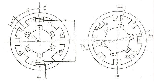
Consider a 4 phase, (8/6 pole) single stack variable reluctance motor shown in the figure below.
variable-reluctance-motor-fig-2
The opposite poles are connected in series forming a 4 phases. The rotor as 6 poles. Here I am considering only phase A to make the connection simple. When the coil AA’ is excited the rotor teeth 1 and 4 are aligned along the axis of the winding of the phase A. Thus, the rotor occupies the position as shown in the above figure (a).
Now, the phase A is de-energized, and the phase winding B is energized. The rotor teeth 3 and 6 get aligned along the axis of phase B. The rotor moves a step of phase angle of 15 degrees in the clockwise direction. Further, the phase B is de-energized, and the winding C is excited. The rotor moves again 15⁰ phase angle.
The sequence A, B, C, D, A is followed, and the four steps of rotation are completed, and the rotor moves 60 degrees in clockwise direction. For one complete revolution of the rotor 24 steps are required. Thus, any desired step angle can be obtained by choosing different combinations of the number of rotor teeth and stator exciting coils.

2019年12月31日星期二

The difference between 0.9 and 1.8 degree step size

On my Prusa Mendel RepRap I have nema 17 stepper motors. I get them off Ebay, straight from the factory. Like something out of Home Improvement, I went a little over the top and got steppers that are a tad overpowered for 3D printing. But, I love them, they barely break a sweat or heat up even after hours of printing.

Stepper motors are a little different from most electric motors. Rather than just spin, they have the ability to ‘step’ and perform fairly accurate partial rotations. These steps make it very easy to tell your stepper motor to rotate say only 7.2°. This is really important for 3D printing, as a big element of 3D printing is just about making lots of these small, precise movements.

image
The super power Wantai stepper motors that I run on my RepRap can make 200 steps in a single rotation, this means the smallest rotation they can possible do is 1.8°. I found some other stepper motors that can do a massive 400 steps a rotation, and got me wondering. If I upgraded my stepper motors, will I notice much of an improvement in print accuracy and quality? So I fired off a question to the now defunct Makers Stackexchange. Soon after, the awesome Adam Davis replied with the following answer.

The Answer:
The tradeoff, mechanically, between the two resolutions is typically a small decrease in torque due to the way stepper motors are designed.  You can compensate with higher currents or larger motors if needed.  You also need to double the speed of your driver to maintain the same machine speed if you go with a finer resolution stepper.  Check out and compare the motor specifications to see this effect as you move from one resolution to another in the same size motor package.

Further, current electronics packages and firmware tend to be designed for lower resolution, faster machines.  As such there are reports that you can only go up to 1/8 microstepping on the higher resolution steppers.  If you have 1/8 on the high resolution stepper, and 1/16 on the low resolution stepper, you end up with nearly the same effective resolution.

At this point in time the practical answer to the “will I get better/faster prints from a 0.9 degree stepper motor” is no.  If one costs less than the other, you might choose based on price.  If you are experimenting with high resolution, slow printing and you are writing your own controller firmware, then you might gain some benefit from the 0.9 degree steppers.

https://www.smore.com/20exh-the-basic-idea-of-electric-motors
http://lindada.freeblog.biz/2019/10/26/what-is-the-difference-between-a-stepper-motor-and-a-common-motor/


Mechanical components that complement gear motors

Stepper motor gearbox are composed of an electric motor and gears, which form the kinematic chain – the fundamental component of the gear ratio.


Kinematic chain
A motor’s speed reducer is composed of a speed reducer and its gears.

This speed reducer is basically a variable speed drive that allows for the speed to be reduced and increased at the output shaft.

Gears
Gears are toothed wheels made of metal or plastic (and new materials with each passing day) that transmit motion when meshing with each other.

They are defined by their number of teeth and their size. In addition, they may have straight-cut or helical teeth.

Do you want to know more about gears? Check out this post.

Motors
The five types of motors that see the most use in gear motors are:

Brushed motors, with brushes normally made out of carbon. They are bidirectional and may be used with DC or AC. They have a service life of about 3000 hours.
Asynchronous motors, which are brushless single-direction motors. They are highly limited.
Synchronous brushless motors, which may be single-direction or bidirectional. They have a constant speed if the frequency of the power source is stable.
Brushless DC motors that use a driver and can attain high speeds.
Stepper DC brushless motors. They can be positioned with an average precision of 7.5º.
If you want to know more: Speed reducers: main applications and how to improve their operation

CLR’s gear motors: their features:
Have you ever wondered where you could buy a gear motor? Then you should know that at CLR were have a track record of over 20 years designing and manufacturing gear motors.

This experience allows us to offer the best actuator solutions for each company. Our product catalog includes the most common electric gear motor models on the market, which additionally have specific user-defined characteristics based on the use that they will be given.(nema 14 planetary gearbox)