2020年1月16日星期四

Oyostepper's Closed-Loop Stepper Motor Market Is Steadily Growth

The global stepper motor closed-loop market will show steady growth. The main factors driving the growth of the global closed-loop stepper motor market include the rapid growth of automation, the standardization of energy efficiency, the integration of motion control components and the low price compared to it. servo motor. However, operating a closed-loop stepper system at a higher speed is difficult, which is a major factor limiting its global market growth.

23hs41-1804s

The main trends observed in the global closed-loop stepper motor market include regulations for the evolution of energy efficiency and microstepping technology. These energy regulations are primarily developed through global warming and the global ecological environment. In addition, the development of Industry 4.0 is expected to provide tremendous opportunities to promote the growth of the global closed-loop stepper motor market.

The main trend observed in closed loop stepper motors is the integration of wireless communication technologies. Wireless technology is part of the automation that has been nurtured over the past decade. Although initial control is inconvenient, wireless technology has evolved rapidly from sensor-only to closed-loop control.

Closed-loop steppers can exhibit mechanical resonance at higher speeds and at specific step rates, so they can lose torque and synchronization. The development of microstepping technology has been seen as another major trend in the global closed-loop stepper motor market. Microstepping technology helps the motor run smoothly and overcomes several cogging and resonance related problems. This technology provides low-cost privileges for closed-loop steppers to improve their performance.


2020年1月15日星期三

Linear actuator falls into two basic categories

A linear stepper motor actuator is an actuator that creates motion in a straight line, in contrast to the circular motion of a conventional electric motor. Linear actuators are used in machine tools and industrial machinery, in computer peripherals such as disk drives and printers, in valves and dampers, and in many other places where linear motion is required. Hydraulic or pneumatic cylinders inherently produce linear motion. Many other mechanisms are used to generate linear motion from a rotating motor.


Linear actuator falls into two basic categories: belts type and ball screws type.

Belt type linear module mainly consists of: belt, linear guide, aluminum alloy profile, coupling, motor, photoelectric switch, etc.

Ball screw linear module mainly consists of: ball screw, linear guide rail, aluminum alloy profile, ball screw support seat, coupling, motor, photoelectric switch, etc.

Industry application field

Linear modules are widely used in dispensing; precision positioning and inspection of semiconductor liquid crystal devices; medical precision analyzer platform; machine tool industry (laser, EMD EDM); wafer inspection, three-coordinate inspection machine; large-scale printing, scanning, 3D printing Manufacturing, processing, experimental equipment; semiconductor manufacturing equipment; flat panel display (FPD) precision testing equipment; laser equipment, machine vision testing equipment; electronic components, PCB testing equipment; logistics equipment and other industries.

23LS26-25042-250E


MCB series linear sliding table typical application case:

Automated stepper motor assembly line X-axis Y-axis Z-axis linear slide

X axis:

1, effective stroke: 500mm

2, Repeat positioning accuracy: ±0.01mm

3, Speed: 100-200mm/s

4, ball screw: C7φ12

5, encoder resolution: 20000 pulses / circle

6, X-axis load 15KG

Y axis:

1, effective stroke: 500mm

2, Repeat positioning accuracy: ±0.01mm

3, Speed: 100-200mm/s

4, ball screw: C7φ12

5, encoder resolution: 20000 pulses / circle

6, X-axis load 15KG

Z axis:

1, effective stroke: 200mm

2, repeated positioning accuracy: ± 0.01mm

3, Speed: 50-100mm/s

4, ball screw: C7φ12

5, encoder resolution: 20000 pulses / circle

6, X-axis load 10KG2

How to Generate Power with a Step Motor
How to Choose a Excellent Extruder Stepping Motor for 3D Printer


2020年1月14日星期二

The principle of Variable Reluctance Stepper Motor

The principle of Variable Reluctance Stepper Motor is based on the property of the flux lines which capture the low reluctance path. The stator and the rotor of the motor are aligned in such a way that the magnetic reluctance is minimum. There are two types of the Variable Reluctance Stepper Motor. They are as follows
Working of a Variable Reluctance Stepper Motor
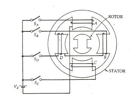
A four phase stepper motor or (4/2 pole), single stack variable reluctance stepper motor is shown below. Here, (4/2 pole) means that the stator has four poles and the rotor has two poles.
Variable Reluctance Stepper Motor fig 1
The four phases A, B, C and D are connected to the DC source with the help of a semiconductor, switches SA, SB, SC and SD respectively as shown in the above figure. The phase windings of the stator are energized in the sequence A, B, C, D, A. The rotor aligns itself with the axis of phase A as the winding A is energized. The rotor is stable in this position and cannot move until phase A is de-energized.
Now, the phase B is excited and phase A is disconnected. The rotor moves 90 degrees in the clockwise direction to align with the resultant air gap field which lies along the axis of phase B. Similarly the phase C is energized, and the phase B is disconnected, and the rotor moves again in 90 degrees to align itself with the axis of the phase
Thus, as the Phases are excited in the order as A, B, C, D, A, the rotor moves 90 degrees at each transition step in the clockwise direction. The rotor completes one revolution in 4 steps. The direction of the rotation depends on the sequence of switching the phase and does not depend on the direction of the current flowing through the phase. Thus, the direction can be reversed by changing the phase sequence like A, D, C, B, A.
The magnitude of the step angle of the variable reluctance motor is given as
variable-reluctance-stepper-motor-eq-1
Where,
  • α is the step angle
  • ms is the number of stator phases
  • Nr is the number of rotor teeth
The step angle is expressed as shown below.
variable-reluctance-stepper-motor-eq-2
Where, NS is the stator poles
The step angle can be reduced from 90 degrees to 45 degrees in a clockwise direction by exciting the phase in the sequence A, A+B, B, B+C, C, C+ D, D, D+A, A.
Similarly, if the sequence is reversed as A, A+D, D, D+C, C, C+B, B, B+A, A, the rotor rotates at step angle of 45 degrees in the anticlockwise direction.
Here, (A+B) means that the phase windings A and B both are energized together. The resultant field is the midway of the two poles. i.e. it makes an angle of 45 degrees with the axis of the pole in the clockwise direction. This method of shifting excitation from one phase to another is known as Microstepping.By using Stepper Motor, lower values of the step angle can be obtained with numbers of poles on the stator.
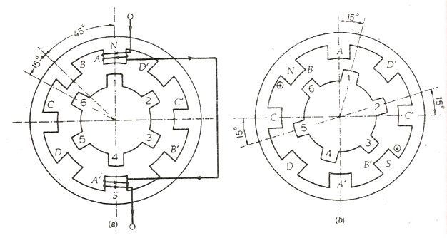
Consider a 4 phase, (8/6 pole) single stack variable reluctance motor shown in the figure below.
variable-reluctance-motor-fig-2
The opposite poles are connected in series forming a 4 phases. The rotor as 6 poles. Here I am considering only phase A to make the connection simple. When the coil AA’ is excited the rotor teeth 1 and 4 are aligned along the axis of the winding of the phase A. Thus, the rotor occupies the position as shown in the above figure (a).
Now, the phase A is de-energized, and the phase winding B is energized. The rotor teeth 3 and 6 get aligned along the axis of phase B. The rotor moves a step of phase angle of 15 degrees in the clockwise direction. Further, the phase B is de-energized, and the winding C is excited. The rotor moves again 15⁰ phase angle.
The sequence A, B, C, D, A is followed, and the four steps of rotation are completed, and the rotor moves 60 degrees in clockwise direction. For one complete revolution of the rotor 24 steps are required. Thus, any desired step angle can be obtained by choosing different combinations of the number of rotor teeth and stator exciting coils.